UART and TTL Introduction
When we make the Bluetooth module testing, the Bluetooth communication will use UART, SPI, and I2C and TTL.
What’s UART
UART is a Universal Asynchronous Receiver/Transmitter (usually called UART), which is a serial asynchronous transceiver protocol.
What’s TTL
The TTL level signal stipulates that +5V is equivalent to logic "1", and 0V is equivalent to logic "0" (when binary is used to represent data). Such a data communication and level specification method is called a TTL (transistor-transistor logic level) signal system. This is a standard technique for communication between parts within a device controlled by a computer processor.
The full name of TTL integrated circuits is Transistor-Transistor Logic, which mainly includes 54/74 series standard TTL, high-speed TTL (H-TTL), low-power TTL (L-TTL), Xiao There are five series of special type TTL (S-TTL) and low-power Schottky type TTL (LS-TTL).
Simply put, UART, SPI, I2C, etc. can be classified into one category, and TTL, RS232, RS485, etc. can be classified into another category. In fact, RS232 and RS485 are more complicated than TTL. After all, the former is an interface standard for serial data communication, while TTL is only a level standard.
UART and TTL are completely different things:
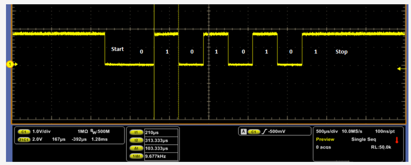
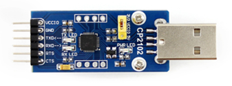
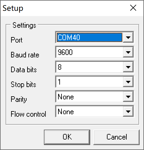
CP2102 USB UART Board as an example, Take the most commonly used serial port configuration: 9600 8N1 (9600 baud rate, 8 data bits, no parity bit, 1 stop bit) to send 1 byte 0xAA as an example.
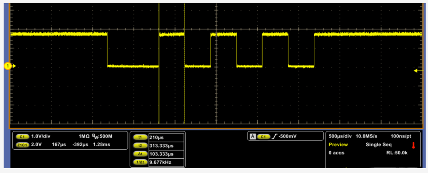
The baud rate is 9600, the theoretical duration of 1bit is 1/9600=104.166us, and the actual measurement is 103.333us
Interpret uart signal
As a kind of asynchronous serial communication protocol, UART works by transmitting each character of the transmitted data bit by bit.
The meanings of each of them are as follows:
Start bit:First send out a logic "0" signal, indicating the beginning of the transmission character.
Data bit:Immediately after the start bit. The number of data bits can be 4, 5, 6, 7, 8, etc. to form a character. Usually ASCII code is used. The transmission starts from the lowest bit and is positioned by the clock.
Parity bit:After adding this bit to the data bit, the number of "1" bits should be even (even parity) or odd (odd parity), so as to verify the correctness of data transmission.
Stop bit:It is the end mark of a character data. Can be 1-bit, 1.5-bit, 2-bit high level. Since the data is timed on the transmission line, and each device has its own clock, it is likely that there will be a small out-of-sync between the two devices in the communication.
So the stop bit not only indicates the end of the transfer, but also provides the computer with an opportunity to correct the clock synchronization. The more bits available for stop bits, the greater the tolerance for different clock synchronizations, but the slower the data transfer rate.
Idle bit: in the logic "1" state, indicating that there is no data transmission on the current line.

The received 8bit data is 0101 0101 , because the low order is transmitted first, convert it to 1010 1010 => 0xAA


