
8 Things You Should Know About Bluetooth Beacon Positioning
Bluetooth® technology has been used to provide various types of location-based services. The location services include Proximity Solutions and Location Systems.
Proximity solutions include point-of-interest (PoI) information solutions, such as in museums application, it provides users with information about artifacts in a room. This category also includes item-finding solutions such as Bluetooth tags that help find lost or misplaced items such as keys, wallets, and more.
Positioning systems, utilize Bluetooth to find the physical location of a device. The main use cases for positioning systems include real-time positioning systems and indoor positioning systems. Real-time positioning systems are used for asset tracking and people tracking, while indoor positioning systems are used to implement wayfinding solutions that help people navigate complex indoor environments.
In the world of Bluetooth-connected devices, Find Me profiles help people find lost items with special Bluetooth tags, while Proximity profiles help people keep important items nearby and find them when they've moved too far. Both of these are examples of Bluetooth standards suitable for project finding use cases.
Retail was one of the first industries to see the potential of Bluetooth beacons, and it has become common to deploy Bluetooth beacons in shopping centres, major department stores and prestigious shopping venues such as Regent Street in London. Typically, a retailer's smartphone app will respond to identifying beacon transmissions containing an ID by notifying users of special offers from nearby stores or departments where the beacon has been installed. Retailers can also get information about customer traffic within the store.
At present, beacons can be found in a variety of situations, providing location and proximity services at airports, art galleries, train stations, stadiums and more.
How does it work of the current Bluetooth beacon technology in positioning?
1. Distance calculation
APP needs to estimate the distance between the smartphone user and the beacon that received the broadcast transmission. Both iBeacon and Eddystone include a reference TX power value in their messages, which informs the application of the expected signal strength at some fixed distance from the beacon, such as when one meter away from the beacon. Then, the basis for estimating the distance to a single beacon is to perform a calculation using the reference signal strength and the received signal strength (RSSI).
2. Positioning accuracy
In fact, pinpointing people in buildings using beacon technology is not easy. Receiving beacon information simply means that the user's smartphone is somewhere within range of the beacon. The direction of the beacon signal cannot be determined, the person may be anywhere in a more or less circular area around the beacon, and the distance from the beacon cannot be determined precisely.
As a result, more advanced solutions must use multiple beacons and more complex algorithms, based on techniques such as trilateration, to more accurately determine location. Of course, even with this more sophisticated approach, there are limits to the accuracy of the position and orientation information that can be derived.
3. Bluetooth direction finding
Bluetooth direction finding methods include AOA and AOD.
With AoA, the receiver contains a multi-antenna array Ao. In each case, a special direction finding signal is sent by one device to the receiver, which is then used by the other device to calculate the direction of the received signal.

With AoD, the transmitting device contains an antenna array

4. Direction finding theory
a. wave cycle
A wave has a repeating pattern with peaks and troughs of maximum and minimum amplitude. Each repetition of the wave as it travels from a peak of zero amplitude down through a valley of zero amplitude and back to zero is called a wave period.

b. wavelength
Wavelength refers to measuring the distance between the beginning and end of a complete wave cycle. Depending on the frequency, Bluetooth has a wavelength of about 12.5 cm.

c. frequency
Bluetooth operates on the Industrial Scientific and Medical (ISM) frequency band from 2.40GHz to 2.41GHz. Bluetooth Low Energy (LE) divides this frequency band into 40 channels, each 2MHz wide. When connected, the device uses 37 available channels, and frequency changes are driven by an adaptive frequency hopping algorithm. In the connectionless case, all 40 radio channels will be used when using extended advertisements introduced in the Bluetooth Core Specification v5.0. Therefore, using Bluetooth to communicate involves many different frequencies, not just one fixed frequency. Wavelength is very important in Bluetooth direction finding and it changes depending on the frequency used.

d. phase
A specific point in a wave's cycle (perhaps measured as the wave passes through an antenna) is called its phase. Phase is measured as the angle from 0 at the beginning of the wave period to 360 degrees or 2π radians at the end of the wave period. Figure 8 illustrates the concept of stages.

e. using Phase to confirm Signal Direction
When a transmitter emits a signal, it travels outward from the transmitter at the speed of light in three dimensions, in the absence of obstacles or other factors that might hinder it. Its path traces an expanding sphere whose surface wavefront amplitude steadily decreases as the energy contained in the transmission spreads over an increasingly larger surface area. As the sphere grows in size, it gets farther and farther from the emitter.
Imagine that,an antenna placed in the signal path, as a wave passes through it, the phase of that wave will change continuously from 0 degrees to 360 degrees.
If we measure the phase at a given instant (t), the phase will have a value called p1.
If we put another antenna in the signal path, somewhere on the circumference of the circle where the TX passes through the first antenna, then the second antenna must be exactly the same distance from the transmitter as the first antenna.
Assuming that each antenna has the same wave passing at the same frequency and therefore the same wavelength, if we simultaneously measure the phase of the radio wave passing through the second antenna, the measured phase (p2) should be equal to p1.

If we move the second antenna closer to the transmitter, taking care to ensure that the difference between the distance from Antenna 1 to the transmitter and the distance from Antenna 2 to the transmitter is not an exact multiple of the wavelength, then if we are in time (t) Measure p1 and p2, we will get different phase values at each of the two antennas.
If we know the distance between the two antennas (on a straight line), the phase difference (p2-p1) and the wavelength of the signal, then we can use basic trigonometry to calculate the angle of the signal.


5. Sampling from different antenna
Bluetooth direction finding technology utilizes specially crafted direction finding signals. A device that receives one of these signals does so by making numerous phase and amplitude measurements at precise intervals in a process called in-phase quadrature sampling, or IQ sampling for short. A single IQ sample consists of the amplitude and phase angle of the wave, expressed as a set of Cartesian coordinates. Applications can convert this Cartesian representation to the corresponding polar coordinates, resulting in phase angle and amplitude values.
When performing IQ sampling in an (I,Q) device with an antenna array, each sample captured must be attributed to a specific antenna in the array.
In the case of AoA, the receiver contains an array of antennas that will perform IQ sampling from each antenna in the proper order.
In the case of AoD, it is the transmitter that contains the antenna array, but it is still the receiver that performs the IQ sampling, taking measurements from its single antenna, and using the design details of the antenna array in the remote transmitter, attribute the measurement to the transmit Machine Figure 12 - Phase Angle and Amplitude (I, Q) Cartesian Coordinate Arrays and Direction Calculations for Specific Antennas. Therefore, for AoD to work, there needs to be a way to provide the receiver with details of the antenna array in the transmitter.

6. Antenna array
Antenna arrays come in a variety of designs and antenna counts.

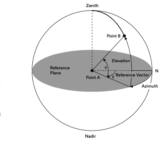
Simple linear designs, like ULA, allow a single angle to be calculated from the signal. More complex antenna array designs can derive two or even three angles. For example, it is often necessary to calculate the elevation and azimuth angles of the signal relative to the reference plane.
The intersection of the lines described by these angles can be used to pinpoint the position of the receiver device in centimeters.
7. Direction finding applications and solutions
The enhancements to the LE controller in the Bluetooth v5.1 allow for the production of raw materials for direction finding through the constant pitch extension and IQ sampling functions of the link layer. In addition to this, to create a direction finding application, the application itself is responsible for several issues, most of which will be covered by a future profile specification published by the Bluetooth SIG. Details will vary depending on the use case the application is based on, but common application considerations include:
a. Determine the location of the beacon
Indoor positioning requires applications to determine the precise location of the beacons they encounter in order to calculate the position of the tracked device (usually a smartphone) relative to the beacon's known location.
In some cases, it may be necessary to locate the beacon in three dimensions in order to know its (x,y) coordinates in the horizontal plane and its elevation above or below some reference altitude. The global coordinate system can be used, or other local coordinate systems can be used.
An application can calculate the location of its host device only if it knows the direction of the received signal, the approximate distance to that beacon, and the location of the beacon.
GATT Indoor Location Services can provide this information.
b. Determine the point of interest (PoI: Point of Interest)
In point-of-interest proximity applications, it is necessary to determine one or more points of interest in the vicinity of the calculated location.
c. Mobile phone direction
In applications involving smartphones, the application may need to take into account the orientation of the phone in 3D space when calculating the signal direction.
d. Determine the details of the antenna array
To properly acquire and process IQ sample data, the application needs to have a description of the antenna array in either the local device (AoA) or the remote device (AoD). The configuration file will describe how the application can get the antenna array description from the remote device, it is expected that the API will be present in this case as well as to get the details of the antenna array in the local device.
e. Configure CTE
Parameters There are various parameters that control CTE production, such as the number of data packets including CTE to be sent in each periodic advertisement event, the length of the CTE, the length of the antenna switching pattern, and the like. These parameters can be set via new HCI commands, and the platform is expected to add APIs that enable applications to do so.
f. Configure and enable IQ sampling
If sampling is to be performed, it must be configured and started. A series of parameters are defined, including the duration of the sampling time slot (1 μs or 2 μs), the length of the switching pattern, and the antenna ID to be included in the sampling pattern.
f. Algorithms and Calculation of Angles from IQ Sample Data There is a range from mathematically simple methods to deriving angles from IQ samples to more complex multidimensional methods that calculate multiple angles and use their intersections to precisely determine the location. The Bluetooth SIG does not specify an algorithm as the standard direction finding algorithm, so choosing the return content algorithm is left to the application layer. It is believed that this is an area where manufacturers and developers can compete. It should be noted that, where appropriate, profiles covering other application issues listed in this section will be published to ensure interoperability is protected.
8. The ways of calculating position from radio signals.
a. angle + estimated distance
Using this method, the location of the device can be estimated by calculating the angle of the received direction finding signal from a single transmitter and by estimating the distance to the transmitter by performing a path loss calculation on the received signal strength indicator (RSSI).
Estimating distance using RSSI provides a relatively rough estimate of distance, so RSSI-based location calculations will not yield the most accurate results. Possibly they are suitable for many applications, the advantage of this approach is that the simplest components are required, such as the use of uniform linear antenna arrays.
The angle is precisely calculated, but there is a greater degree of uncertainty in the distance from the transmitter.
When using the angle-plus-distance estimation method, the accuracy of location determination can be improved by deploying multiple beacons to cover a given physical space and using trilateration to determine the area where the location areas calculated with reference to each beacon intersect.

b. multi-angle intersection

Contact Us
Anne +86 13480952801
Lynn +86 18664368785
 Tel/Whatsapp: +86 18664368785
 E-mail: info@hyxkiot.com
 Skype:+86 18664368785
 Add: Room 502, Building 1, Jinhai Building, 19 Jinhai Road, Xixiang, Baoan District, Shenzhen, Guangdong, China 518102